End windings design
1. Overview - definitions
This part characterizes the end-winding and the resulting conductor dimensions.
For additional information refer to the sections dedicated to the coil and conductor settings and End-winding topology.
| Label | Symbol | Tooltip, note, formula |
| End-winding topology | * | End-winding topology: U-shape, C-shape or Y-shape. |
| C.S. total extension | * | Connection side total extension. |
| C.S. straight extension | * | Connection side straight extension |
| Axial overall length | * | Axial overall length. Length between the two extremities of the winding i.e. between connection side and opposite connection side. |
| O.C.S. total extension | * | Opposite connection side total extension. |
| O.C.S. straight extension | * | Opposite connection side straight extension. |
| Total conductor length | * | Total conductor length. |
| Mean turn length | * | Mean turn length. |
| Coil connection length | * | Additional length corresponding to the connections between coils. |
2. End-winding topology – U-Shape
Topology available for all the 3 winding architectures
 |
|
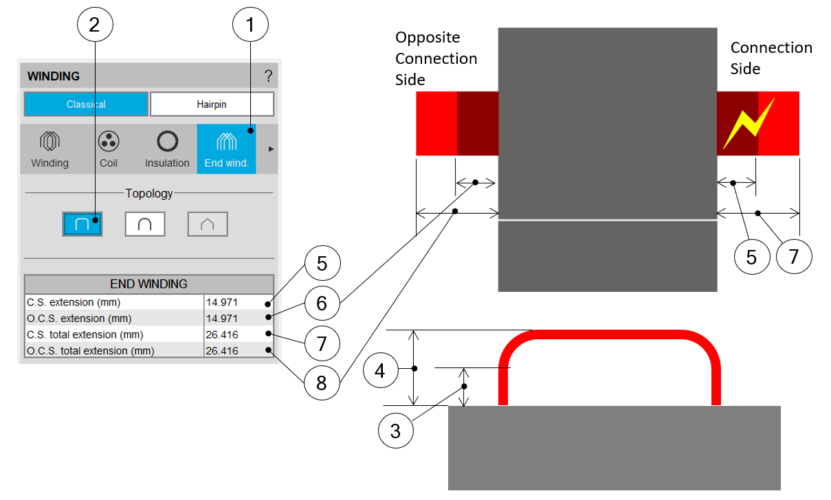
| Building the winding – End-winding topology and dimensionsCase of the U-shape End-winding | |
| 1 | Selection of the END-WINDING tab. |
| 2 | Selection of the U-Shape end-winding case. |
| 3 | Straight extension of the U-Shape end-winding topology = User input parameter. |
| 4 | Total extension of the U-Shape end-winding topology = User input parameter. |
| 5 | Definition of the connection side straight extension (ref. 3). |
| 6 | Definition of the opposite connection straight extension (ref. 3). |
| 7 | Definition of the connection side total extension (ref. 4). |
| 8 | Definition of the opposite connection side total extension (ref. 4). |
3. End-winding topology – C shape
Topologies available for all winding architecture
 |
|
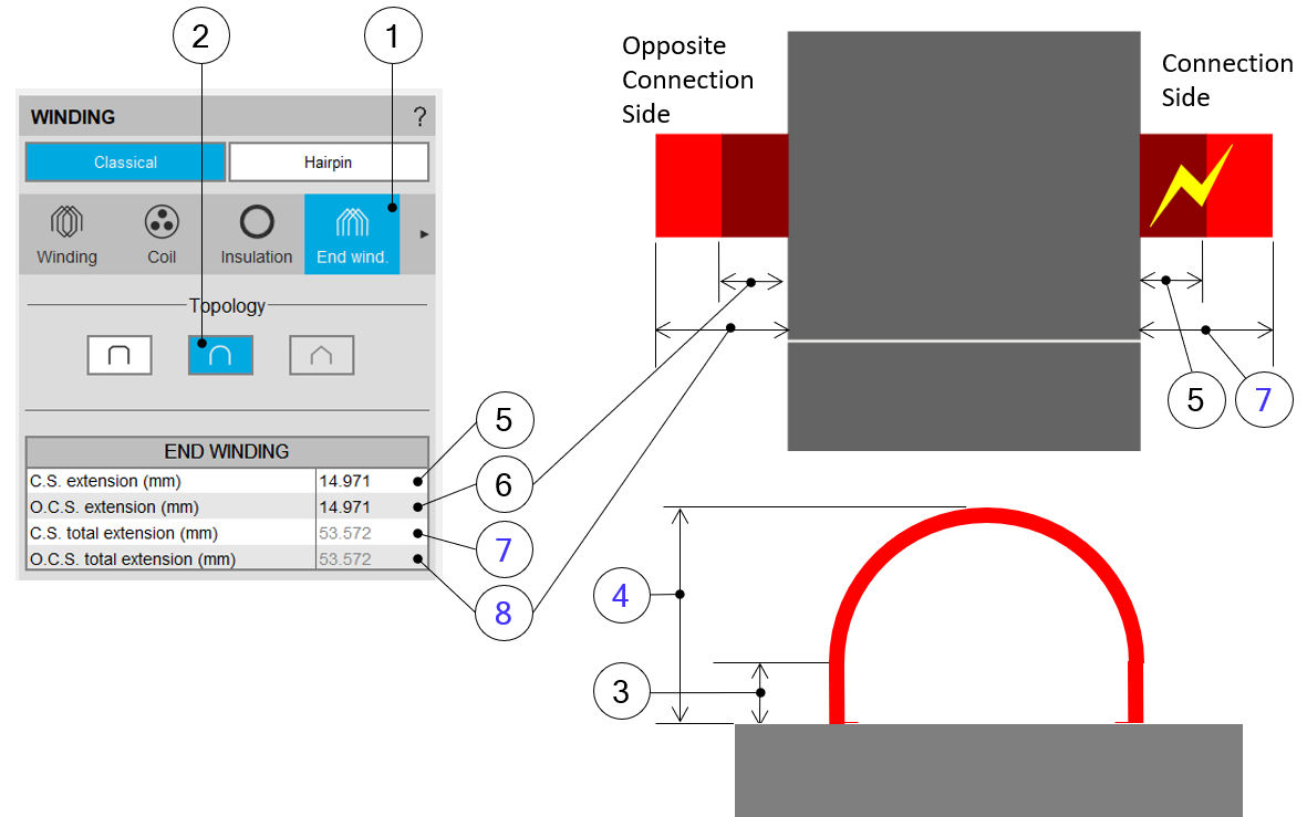
| Building the winding – End-winding topology and dimensionsCase of the C-shape End-winding | |
| 1 | Selection of the END-WINDING tab. |
| 2 | Selection of the C-Shape end-winding topology. |
| 3 | Straight extension of the C-Shape end-winding topology = User input parameter. |
| 4 | Total extension of the C-Shape end-winding topology = Computation result deduced from topology characteristics. |
| 5 | Definition of the connection side straight extension = User input (ref. 3). |
| 6 | Definition of the opposite connection straight extension = User input (ref. 3). |
| 7 | Definition of the connection side total extension = Deduced result (ref. 4). |
| 8 | Definition of the opposite connection side total extension = Deduced result (ref. 4). |
4. End-winding topology – Y shape
This topology is available only with two layers and superimposed coil layout.
 |
|
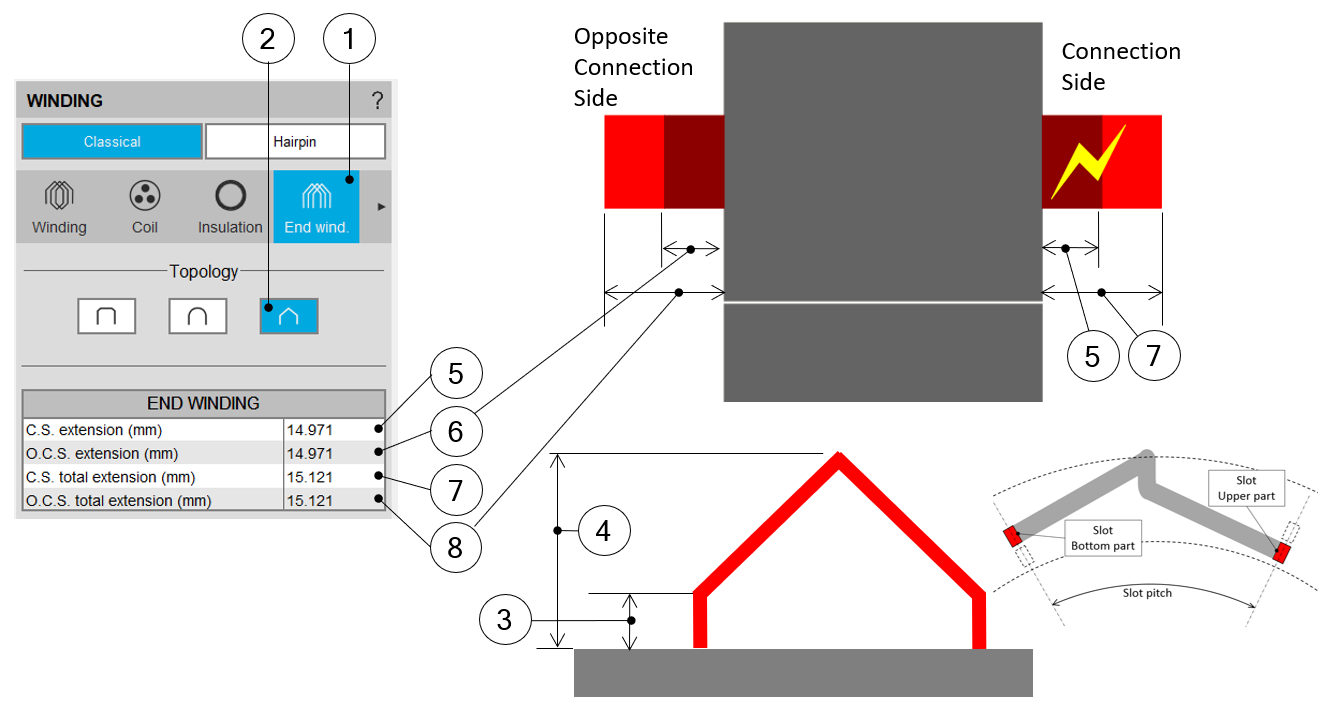
| Building the winding – End-winding topology and dimensionsCase of the Y-shape End-winding | |
| 1 | Selection of the END-WINDING tab. |
| 2 | Selection of the Y-Shape end-winding case. |
| 3 | Straight extension of the Y-Shape end-winding topology = User input parameter. |
| 4 | Total extension of the Y-Shape end-winding topology = User input parameter. |
| 5 | Definition of the connection side straight extension (ref. 3). |
| 6 | Definition of the opposite connection straight extension (ref. 3). |
| 7 | Definition of the connection side total extension (ref. 4). |
| 8 | Definition of the opposite connection side total extension (ref. 4). |